Jun 26, 2026Services Overview
Practical Guide to SMT Pick-and-Place Machine Operations: Proven Techniques to Boost Yield by 15%
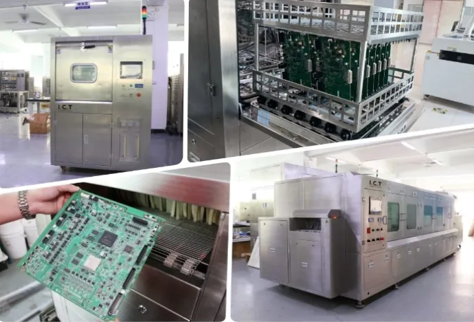
Practical Guide to SMT Pick-and-Place Machine Operations: Proven Techniques to Boost Yield by 15%
In the electronics manufacturing industry, pick-and-place machines serve as the "heartbeat" of any SMT production line, directly determining overall throughput and product quality. Industry statistics confirm that **over 60% of SMT production issues stem from improper machine operation or inadequate maintenance**. This comprehensive guide, validated by over 100,000 electronics manufacturing professionals worldwide in the past three years, provides a complete framework for machine operation, preventive maintenance, and troubleshooting. It empowers frontline technicians to achieve measurable improvements in yield and cost reduction that management can immediately recognize.
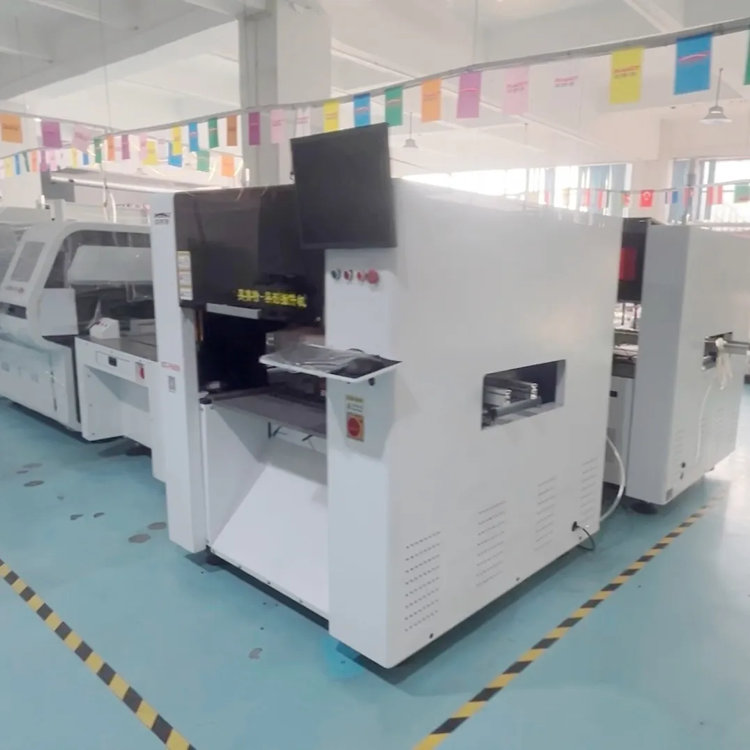
1. The Critical 10-Minute Pre-Startup Routine: Prevent 80% of Production Disruptions
Many operators rush to start production, skipping essential pre-operation checks. This oversight leads to preventable downtime that far exceeds the time saved by cutting corners. **Implementing a rigorous 10-minute pre-startup checklist eliminates more than 80% of equipment failures and production accidents**.
1.1 Environmental and Safety Verification
ESD Compliance: Mandate proper ESD wrist straps and footwear for all personnel. Ensure wrist straps make direct skin contact and are properly grounded. This is the first line of defense against electrostatic discharge damage to sensitive components.
Air Supply Validation: Confirm compressed air pressure remains stable between 0.5–0.6 MPa. Drain accumulated water and oil from air filters and replace filters when contaminated.
Power System Inspection:Verify input voltage is within ±10% of the rated value and ensure all ground connections are secure.
Emergency Stop Testing: Activate all emergency stop buttons sequentially, then release them to confirm proper system response.
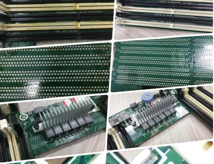
1.2 Mechanical System Inspection
Vision System Maintenance: Gently clean camera lenses and mirrors with lint-free cloths to remove dust and fingerprints. Adjust light intensity if degradation is detected.
Nozzle Assessment: Inspect all nozzles for wear, deformation, or clogging. Replace any nozzle with wear exceeding 0.1mm immediately, as worn nozzles drastically increase component rejection rates.
Conveyor System Check: Manually move the conveyor to ensure smooth operation without unusual noises or jams. Verify conveyor width matches the current PCB specifications.
Feeder Installation**Confirm all feeders are securely mounted and tape tension is properly adjusted (tape should not slide when pulled gently but move freely when pushed).
1.3 Software and Parameter Verification
Program Validation: Cross-reference the active production program with the work order to ensure correct product model and version number.
Parameter Backup: Always back up original parameters before making any modifications to enable rapid recovery if issues arise.
Warm-Up Procedure:Execute a mandatory 10-minute warm-up cycle after powering on the machine. This allows all mechanical components to reach stable operating temperatures, which is critical for maintaining placement accuracy, especially in colder environments.
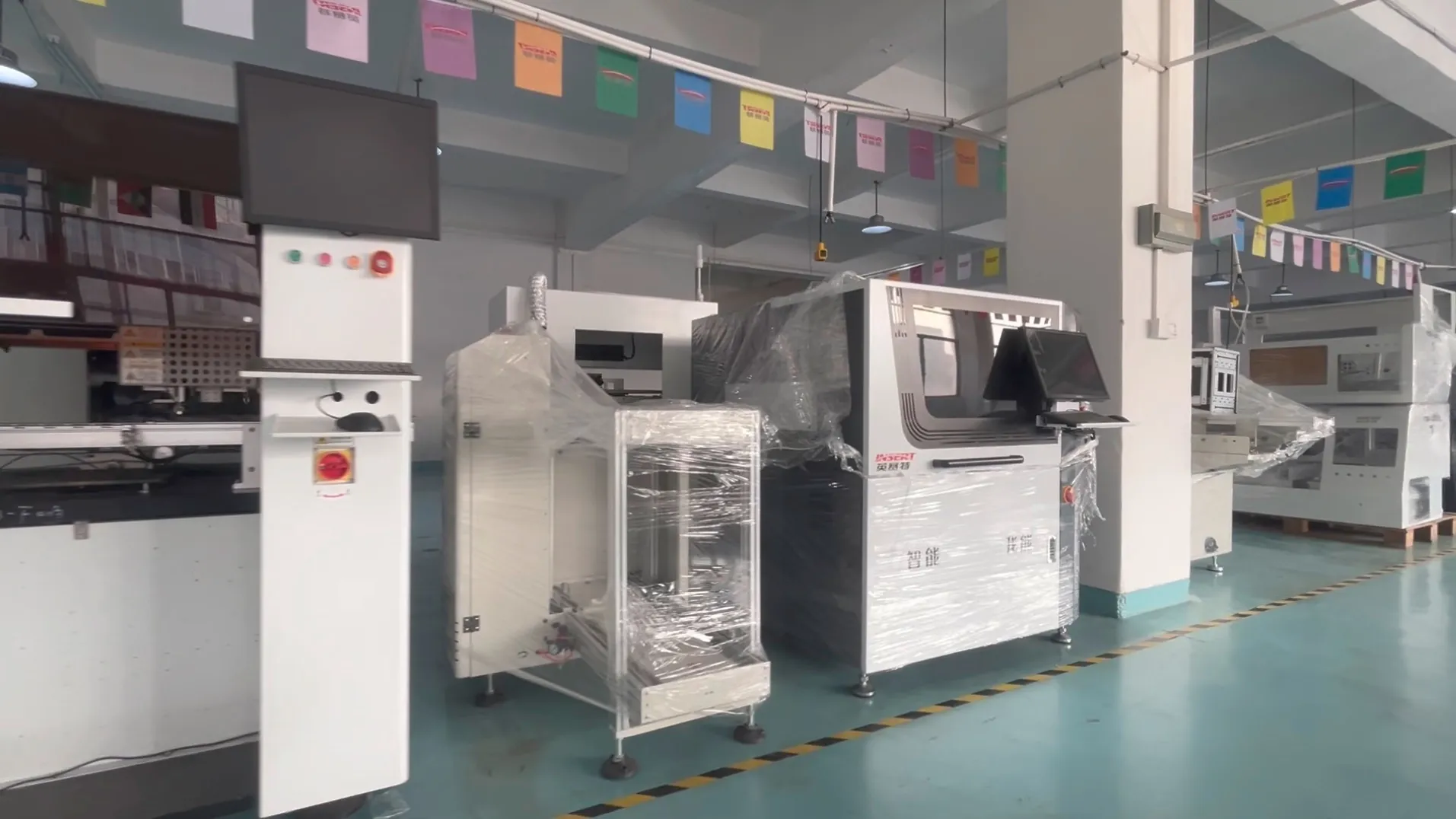
2. Standard Operating Procedures: Every Step Impacts Product Quality
Pick-and-place machine operation is not simply pressing buttons. Each step has precise specifications that directly affect final product quality. Following standardized procedures consistently maintains placement yields above 99.5%。
2.1 Program Import and Calibration
CAD File Integration: Export CSV files from EDA tools containing component designators, footprints, X/Y coordinates, and rotation angles for import into the machine software.
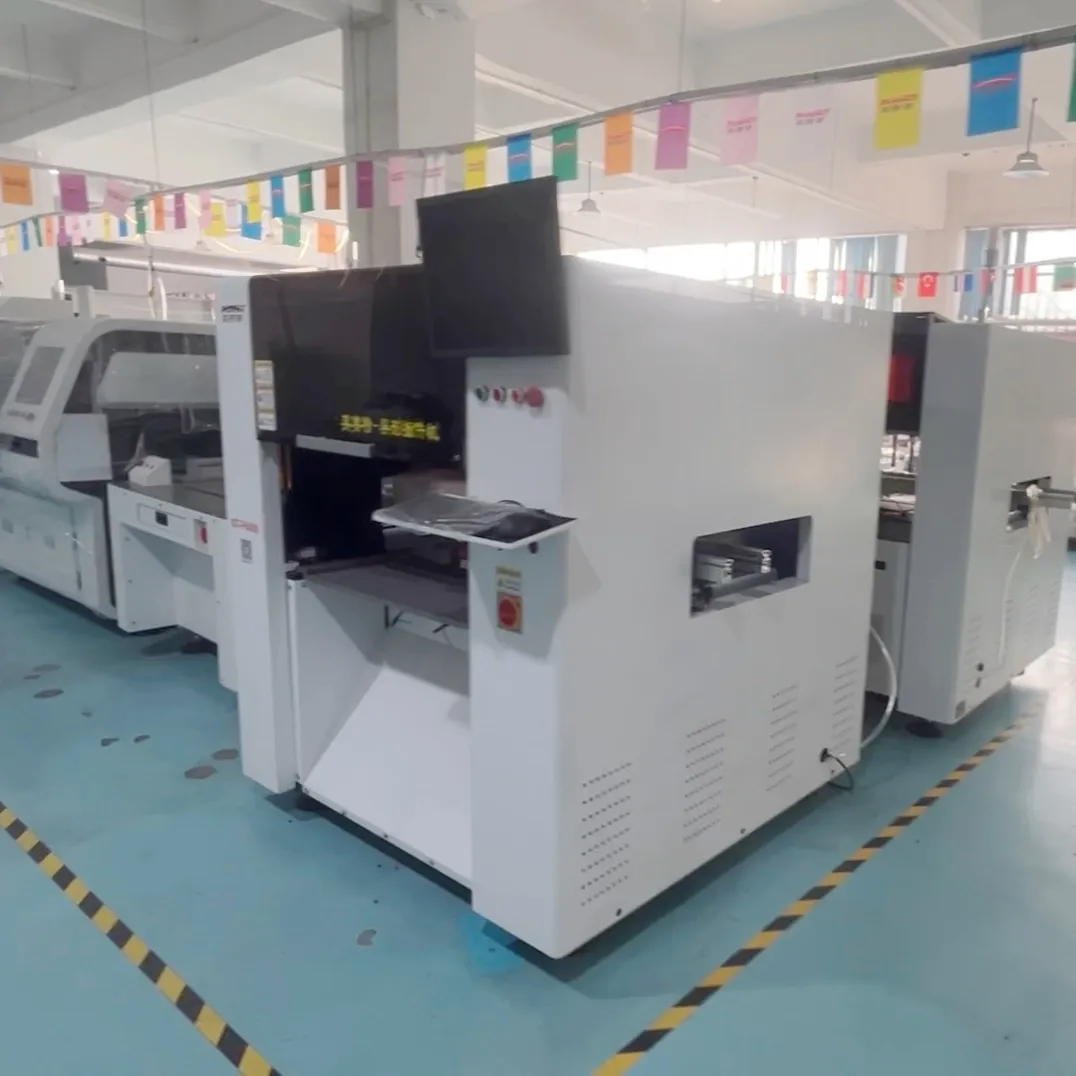
Coordinate System Setup: Define the PCB origin at the lower-left corner to match the CAD file coordinate system.
Fiducial Registration: Manually identify at least two fiducial marks to establish the global transformation matrix. Set the fiducial search window to at least 1.5 times the fiducial diameter.
Component Mapping: Map CAD component types to corresponding IDs in the machine library, paying special attention to component polarity and footprint dimensions.
2.2 First Article Verification
Dry Run Execution: Perform a complete dry run without components to verify placement head trajectories and eliminate collision risks.
First Article Production: Assemble the first PCB and conduct thorough inspection using magnification or AOI equipment to verify component position, polarity, and height.
Parameter Refinement: Adjust placement coordinates if component offset is detected. Modify placement pressure and height if component floating is observed.
Quality Approval: Obtain formal quality assurance approval before initiating mass production.
2.3 Production Process Monitoring
Rejection Rate Tracking: Record component rejection rates hourly. Normal operation should maintain rejection rates below 0.3‰. Investigate immediately if rates spike unexpectedly.
Placement Accuracy Verification: Sample one PCB every two hours to verify placement accuracy remains within tolerance limits.
Equipment Status Monitoring: Continuously monitor machine operation for unusual sounds, vibrations, or alarms. Address anomalies immediately to prevent catastrophic failures.
Material Replenishment: Prepare replacement reels in advance and use splicing tape for non-stop material changes to minimize production interruptions.
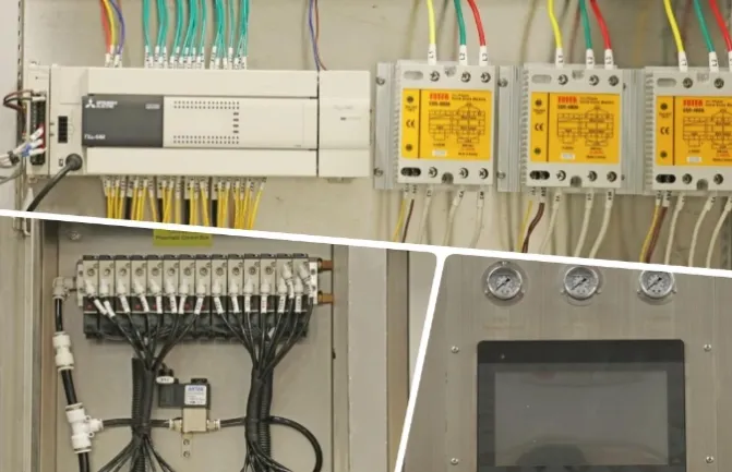
3. Preventive Maintenance Schedule: Extend Equipment Lifespan by 3 Years
Pick-and-place machines are highly precise mechatronic systems.Regular preventive maintenance not only reduces unplanned downtime but also extends equipment lifespan by 3+ years. The following maintenance schedule has been proven effective across thousands of installations.
3.1 Daily Maintenance Tasks
Clean machine surfaces and work areas
Inspect and clean nozzles and nozzle stations
Drain condensate from air filters
Verify vacuum pressure levels
Document equipment parameters and any abnormal conditions
3.2 Weekly Maintenance Tasks
Clean X/Y axis guide rails and sliders
Apply precision instrument grease (e.g., KLUBER Isoflex) to X/Y axis rails
Replace vacuum generator filter elements
Inspect pneumatic circuits for leaks
Calibrate Z-axis height of placement heads
3.3 Monthly Maintenance Tasks
Clean Z-axis ball screws and apply low-volatility silicone grease
Lubricate rotary joint bearings
Check coupling torque on all axes
Calibrate cameras and vision systems
Back up all machine parameters and programs
3.4 Quarterly Maintenance Tasks
Perform servo motor encoder calibration
Inspect and adjust belt tensions
Replace main air filter cartridges
Verify all electrical connections are secure
Conduct comprehensive machine accuracy testing
4. Rapid Troubleshooting for Common Issues: Resolve Problems in 30 Minutes.
Equipment failures are inevitable in production environments. Mastering these troubleshooting techniques reduces average downtime to less than 30 minutes.
4.1 High Component Rejection Rates
Nozzle Issues: Worn, deformed, or clogged nozzles → Clean or replace nozzles.
Vacuum Problems: Insufficient or unstable vacuum pressure → Inspect vacuum generators and lines for leaks.
Feeder Malfunctions: Misaligned feeders or incorrect indexing → Calibrate feeders.
Component Quality: Dimensional variations or poor tape quality → Replace components or adjust component parameters.
Parameter Errors: Incorrect pick height, placement height, or speed settings → Adjust relevant parameters.
4.2 Placement Offset Issues
Fiducial Problems: Poor fiducial recognition or unclear marks → Clean fiducials or adjust recognition parameters.
Camera Issues: Misaligned cameras or dirty lenses → Clean lenses and recalibrate.
Nozzle Centering: Off-center nozzles → Perform nozzle center calibration.
PCB Issues: Warped PCBs or improper positioning → Replace PCBs or adjust fixtures.
Mechanical Play: Excessive backlash in X/Y axis drives → Adjust drive mechanisms.
4.3 Component Floating
Insufficient Placement Pressure: Increase placement pressure.
Excessive Placement Height: Lower placement height.
Solder Paste Issues: High viscosity or excessive paste deposition → Adjust printing parameters.
Component Defects: Foreign material on component bottoms or deformed components → Inspect component quality.
Reflow Issues: Improper reflow temperature profile → Optimize thermal profile.
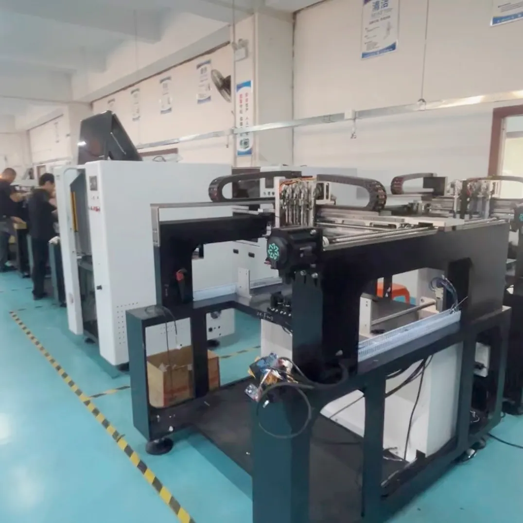
4.4 Machine Alarm Shutdowns
Emergency Stop Activation: Release all emergency stop buttons
Safety Door Interlock: Ensure all safety doors are properly closed
Servo Overload: Check for mechanical obstructions, clear debris, and reset
Power Supply Failure: Verify input power is within specifications
Software Glitches: Restart the machine or reinstall software
Conclusion
Effective operation and maintenance of pick-and-place machines require meticulous attention to detail and adherence to standardized procedures. **Only by following established protocols and implementing regular preventive maintenance can manufacturers ensure consistent equipment performance and high product quality**. The practical techniques outlined in this guide will help electronics manufacturing professionals enhance their technical skills and deliver tangible value to their organizations.